| Shaping
a Fuselage (with flattened sides) Using FSDS. |
For this example I am using the Beech King Air
since it has both a rounded fuselage and flattened sides.
| Step 1 - Just like
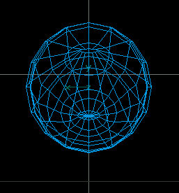
any fuselage I think it's best to start with a tube. Add enough Points
and Sections to cover all of the curves and sections that might be
required. You can add sections later but you can't add sides. Make the
tube approx. as long and as wide as your fuselage will be. Be sure to
check the Close Left... and Close Right... checkboxes
as it's easier to do now that later. Be sure to align it along the Z axis.
fig. 1 |
| fig.1 |
 |
| Step 1 - Starting
with your tube fig.
2, begin shaping
the side ONLY of the fuselage by selecting the points of the first (right)
section fig.
3.
Switch to Scale mode (circled in red fig.
4) and then elect the Constrain
X and Constrain Z buttons (circled in green fig.
4) to resize the
section to the desired size. |
| Step 3 - Alternate
between Scale mode and Move mode to scale and position the
sections as desired. Remember to keep the Constrain X and Constrain
Z buttons selected when resizing. fig.
5 |
| fig.
5 |
 |
| Step 4 - Continue
the process until the length of the fuselage has been completed. fig.
6 |
| fig.
6 |
 |
| Step 5 - Switch to Top
view and continue the resizing process. This time, use the Constrain
Y and Constrain Z buttons
fig. 7.
You should not need to move the sections fore or aft as they should have
been set when sizing in Side view. Continue until you
have resized all sections. Your fuselage basic shape should now be
complete. fig. 8 |
| fig.
7 |
 |
| fig. 8 |
 |
| Step 6 - Switch to
Front view and notice that the sides are almost completely round and not
yet flat like they need to be. fig.
9 (Background
turned off for clarity.)
fig. 9b |
| fig.
9 |
 |
| fig. 9b |
 |
| Step 7 - Switch to Side
view and then Point mode and select the points for side panels
you wish to flatten. Try to get all desired points select. You can select additional
points by holding down the shift key after making your first
selection and then selecting any addition points.
fig. 10 |
| fig.
10 |
 |
| Step 8 - Switch back
to Front view and Go to Scale mode and select the Constrain Y and Constrain
Z buttons. Scale the selected points to the desired location.
In this example, I scaled them inward slightly. Notice
that the fuselage sides begin to flatten.
fig. 11 |
| fig.
11 |
 |
| Step 9 - Continue
the process with other areas until the desired side flatness is achieved.
fig. 12 and
Fig. 12b |
| fig.
12 |
 |
| fig.
12b |
 |
| Step 10 - Continue
the process with other areas until the desired side flatness is complete.
fig. 13 &
14 |
| fig.
13 |
 |
| fig.
14 |
 |
©2000 by David Eckert
Feedback:
If you have time, please fill out
this feedback form. You comments and suggestion will help me to add more
tutorials and improve on the existing ones.
Note: No fields are
required, however, this form is sent via email so your email address will be
revealed to me. I will never: sell, trade or otherwise reveal your email address
to anyone else. (Can you tell that I hate spam?)
If you would like to offer
feedback but do not wish to reveal your email address, feel free to leave a
message on the Aircraft
Design Message Board.
Thanks!
Dave
daviator.com


