| Creating Recessed Gear Wells and Flush Gear Doors in FSDS - Part1 |
Part 1 of this tutorial covers creating recessed
landing gear wells with perfect fitting gear doors.
Part 2 cover animating the gear doors from
the retracted position.
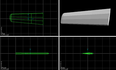
For this exercise, I created a generic wing and gear well. Bright green instead of light blue was used for the current part color because it shows up better in the JPGs created for this tutorial.
it is recommended that you read through the tutorial before attempting the process outlined. This will give you a better understanding of the techniques described here.
Keep in mind, this is one man's opinion and there are may ways to achieve the desired effect.
Requirements:
FSDS and a basic understanding of its use.
Aircraft Animator 1.2e and a basic understanding of its use.
Time and patience.
Note: There are many images on this page
to load so please be patient.
1) Start by creating your wing first. it's
important to place cross sections slightly to the left and right of the desired
gear well location.
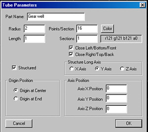
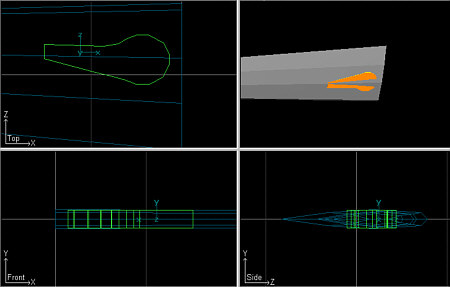
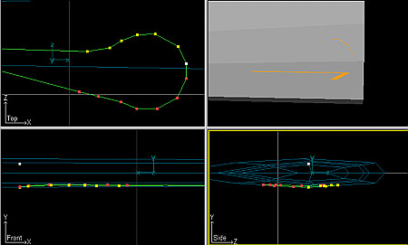
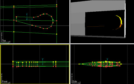
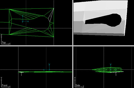
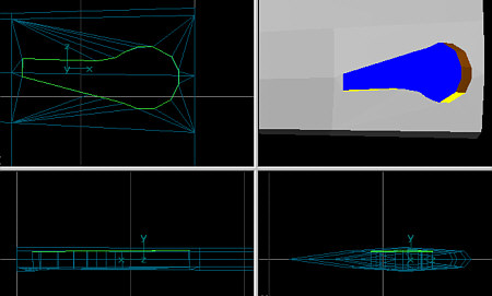
2) The next step is to create the gear well. The gear well will be a shaped tube with the Y as the log axis. Only one section is needed but be sure to add enough Points to shape the well properly.
| Gear Well Parameters | |
 |
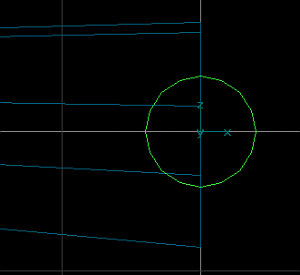 |
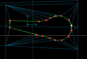
3) Switch to Point Mode > Top View and begin shaping the gear well to the desired shape.
| Top View after Shaping |
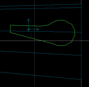 |
| Expanded View after Shaping |
 |
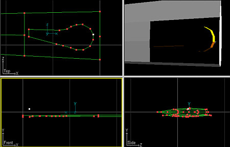
4) The next step is to shape the lower portion of the gear well to align with
the lower part of the wing. To make this easier, let's first hide any points
that may accidentally be selected and moved. Switch to Front View & Point
Mode. Select the upper points of the gear well.
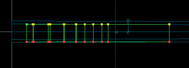
5) Next, go to Edit > Hide Selected and
notice that the points are now safely gone from view.
6) Now, select the Constrain X and Constrain Z
buttons.  This will
prevent any movement of points that can misshape the gear well.
This will
prevent any movement of points that can misshape the gear well.
Move points up or down until the gear well is
barely visible through the lower part of the wing. (Hint: Changing the color of
the gear well makes it easier to see when protruding through the wing surface.
7) Important: Once this step is completed, save each part. In the event of a mistake later on, you can simply reload each part and begin again.
8) The parts must now be joined. With one of
the parts selected, go to Part > Select by Name...
Select each part (wing and gear well) and click OK
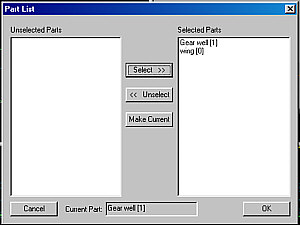
9) Then go to Part > Join Selected. The gear
well and wing will now become one part.
10) The next step is to delete overlapping
polygons. Switch to Polygon Mode and delete the polygons from the wing
section and gear well that overlap each other.
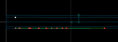
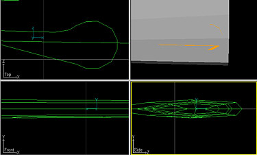
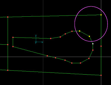
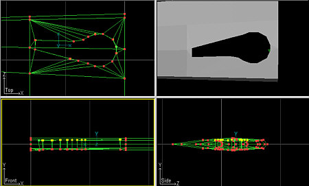
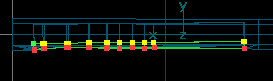
11) Before we can begin creating the new polygons that will be form the new lower wing area, we need to hide any points that may be in the way. Switch to Front View & Point Mode. Select the upper points of the gear well portion of the newly joined part. Go to Edit > Hide selected.
| Selected points to hide. |
 |
|
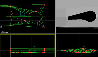
After points have been hidden. |
 |
12) Once the non-needed
points are safely hidden, we can begin the process of forming the newer lower
portion of the wing. Switch to Point mode, select 3 points that
form a triangle then go to Polygon > Make Poly from Selected
points.
13) Continue the process until all gaps have
been replaced.
Note: Some polygons may be facing the wrong direction and may need to be
flipped.
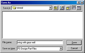
14) Save the new wing as a part. (Example: wing
with gear well)
15) In order to probably texture the gear well
and wing, it is now necessary to break apart the wing, gear well sides and gear
well floor. After saving the part, switch to Point Mode and delete the parts
that make up the upper portion of the gear well.
this will eliminate the gear well sides and floor leaving the wing intact with
the correct cutout for the gear well. the wing can then be textured by
itself.
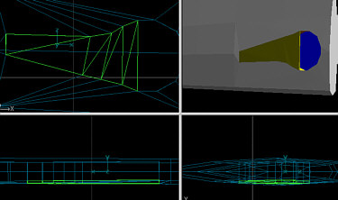
16) Now you can create the gear well sides. Go
to Part > Load... and select the "wing with gear well" part. 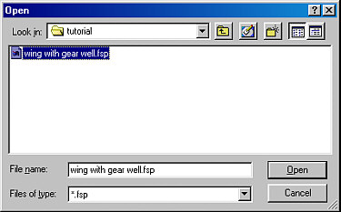
17) Switch to point mode and delete all points except
those forming the shape of the gear well. This will leave the gear well as a separate
part.
Note: You will need to go to
Polygon Mode and then to Edit > Select All, and then to Poly > Flip All
Selected to get the polys that form the well facing the correct direction. Be
sure to unselect all when finished.
Delete the polygons) that form the floor of the gear well.
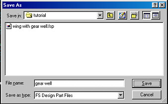
18) Save the resulting part as the new gear
well.
19) Now load the newly created gear well part.
Delete the lower points and then select the points that form the floor of the
well and go to Polygon > Make Poly from Selected Points. (You may need to use
the process described in Step 12 above to avoid concave
polygons and possible flickering in FS2000)
20) You should now have three perfectly fitting
parts that form the wing/gear well:
wing
gear well sides
gear well floor
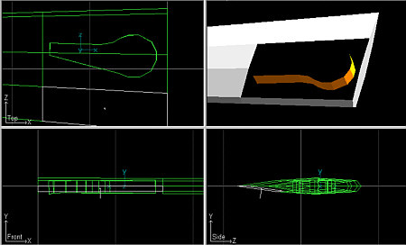
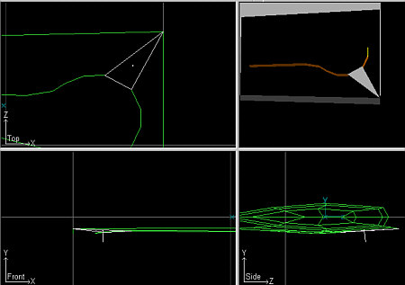
21) The next step is to create the gear doors.
Load the saved gear well part. the door is nothing more that a flattened version
of the gear well. selected the Points that make up the upper portion of the gear
well. Select the Constrain X and Constrain
Z buttons to prevent any unwanted lateral movement of points. Move the points
downward until the desired thickness of the gear is achieved. By leavening the
lower points untouched, you are assured of a perfect fit when the gear are
retracted.
You can then eliminate any points or polys to
form the outer half of the door.
Note: Polygons inevitably get missed or deleted. Be sure to recreate or
flip polys where needed.
Repeat the process for the secondary door.
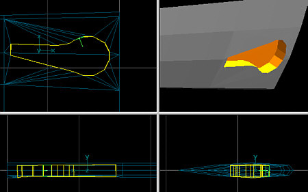
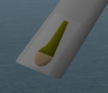
(screenshot of completed gear well and doors.)
Click here to continue to Part 2 - Animating the doors.
©2000 by David Eckert